Posted on
August 4, 2023
Once Blender released Geometry Nodes, I’ve been interested in finding ways to integrate them into other pipelines and workflows. But how do you get Geometry Nodes out of Blender? I spent some time researching the process of exporting data through Blender’s Python APIs and I thought I’d share my findings.
I created a Python script that takes the selected object and exports the data associated with the geometry node modifier. From the nodes, to the connections, to the data inside the nodes — I grab all the data from Blender and generate a JSON file to import into any other app. I’ll talk about developing this script, as well as visualize the Blender API a bit to illustrate the structure of a geometry node in code.
This is a mini tutorial series where I’ll be taking geometry nodes from Blender and using them in different places, like making a React web app to display them. See the final code for this script and the web app here on Github. There’s also an NPM module for the adventurous (npm i react-geometry-node-graph).
What are Geometry Nodes?
It’s important to do a quick into to geometry nodes, since there’s a bit of terminology we’ll be using that it helps to familiarize yourself with.
Geometry Nodes are a feature in Blender that allows artists to use a node graph to power low level 3D creation and transformation. Similar to the node graph used for creating “materials”, the user adds and connects nodes together. The “Geometry Nodes” themselves are just a modifier that’s applied to an object.
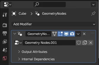
The modifiers panel in Blender showing a Cube with a Geometry Nodes modifier applied.
Each node in the node graph represents functionality the user is running, usually powered by input from another node. For example, you could have a like a “Set Position node” that changes the XYZ position of the “input” geometry. The node then outputs data to another node.
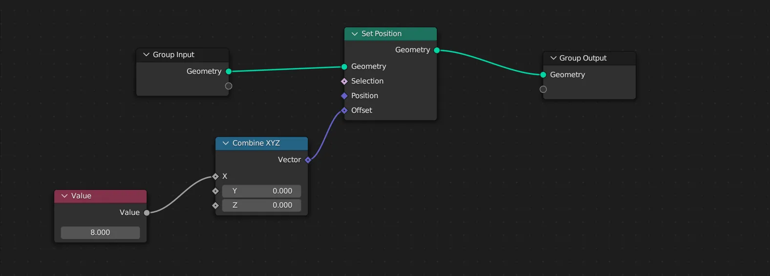
Example of Geometry Nodes in Blender from the node graph editor. Multiple different nodes are connected to each other through various inputs and outputs.
Each node’s input and output (the “sockets” on left and right side) represent different types of data — like geometry, 2D/3D/4D vectors, numbers/floats, etc. You’ll notice above that a geometry input needs to go to a geometry output. This is how nodes work - they take specific types of data, do their magic, then pump out the data (sometimes in a different form — like taking a single number and making a 3D vector).
The nodes connect to a final output node that combines all the node data together. For Geometry Nodes, this is geometry data, such as vertices and their positions, rotations, etc.
This is similar to running a programming script, with each node like a “function” in code that accepts parameters or “input” from the previous function, and all the nodes running like a chain of commands. Unreal Engine does a fantastic job of representing this in their “Blueprint” editor, which is a node graph for running game engine commands (like making a character jump or move). When you run the game you’ll see moving dots on the connections between nodes, letting you know the order they run in - as well as which nodes may be unreachable.
The Unreal Engine Blueprint editor showing the direction of flow in a node graph using animated dots on the connections (source)
All these nodes get applied to your object, transforming your object into whatever the output calculates.
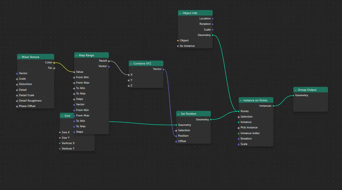
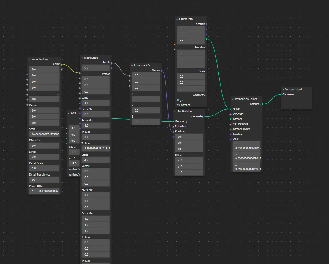
Here’s an example of a geometry node creating a grid-like wave effect. This happens because we take a Grid node and make a 2D plane, then use that as a basis to place other cube meshes as “instances” on the “points” of that grid, and we alter their position using a wave texture. This all gets pumped into a “Group Output” node that displays our altered geometry data.
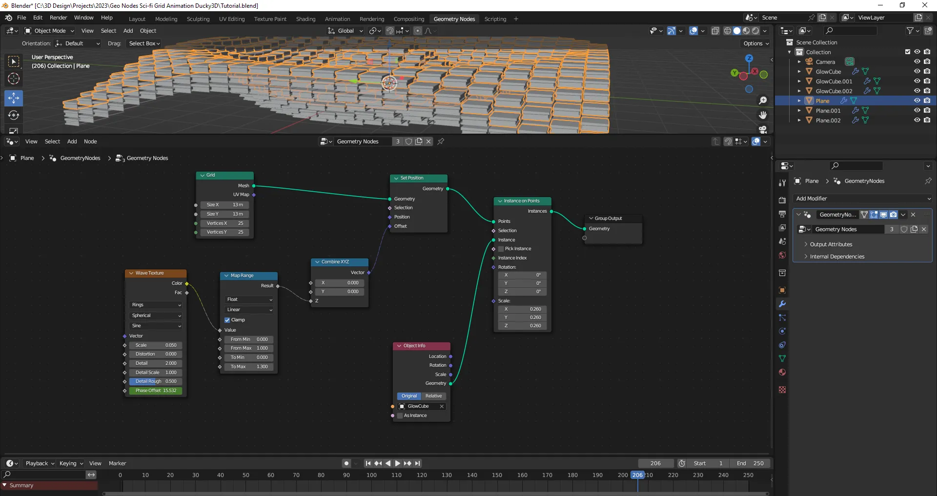
Example of a Geometry Node generating a 3D grid of boxes positioned in a wave-like pattern.
How do you get geometry node data?
Blender provides a Python API that you use to write scripts to change parts of the app (like adding new panels to the UI, or in our case - extract data from geometry). It’s pretty nifty, you can write commands in the Console window to get quick feedback (similar to Python’s built-in console), or you can write full multiline scripts in the Scripting window.
Tips and Tricks
Before we dive too deep, I wanted to give a couple of tips for programming in Blender and Python that helped me wrap my head around it.
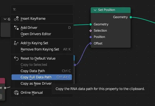
Quickly find data properties in code
To find the geometry node data we’ll need to be digging a little deep into data structures. To make the process of finding things easier, you can quickly find the “path” of any property by right clicking on it and selecting “Copy Full Data Path”.
This will create a dot separated name with the property’s location relative the modifier. For example, the “Y” input on the Combine XYZ node can be found here: bpy.data.node_groups["Geometry Nodes.001"].nodes["Combine XYZ"].inputs[1].default_value. If you get lost at any point in the code and you’re not sure where it is, try this method to orientate yourself.
Console.log
If you want to write a debug statement (similar to console.log in JavaScript), you can use Python’s print() method. But this prints out to your OS’s console, which Blender in newer versions sometimes hides. To fix this, we can define a function that replaces the built-in print() method with our own that also prints the output to the Blender Console window. This way you don’t have to find out how to enable the OS console, and you can have a nice single-screen setup for coding.
import bpy
from bpy import context

import builtins as __builtin__

def console_print(*args, **kwargs):
    for a in context.screen.areas:
        if a.type == 'CONSOLE':
            c = {}
            c['area'] = a
            c['space_data'] = a.spaces.active
            c['region'] = a.regions[-1]
            c['window'] = context.window
            c['screen'] = context.screen
            s = " ".join([str(arg) for arg in args])
            for line in s.split("\n"):
                bpy.ops.console.scrollback_append(c, text=line)

def print(*args, **kwargs):
    """Console print() function."""

    console_print(*args, **kwargs) # to py consoles
    __builtin__.print(*args, **kwargs) # to system console

print("print me to console")
print("and me\n and me", "and me\nI'm:", print)
Shoutout to this StackOverflow post for this great snippet. I just keep this on the top of my scripts to make debugging easier.
Get a list of object or class properties
This one is Python 101, but it’s incredibly useful here so I thought I’d mention it. When you’re dealing with complex data structures (like objects or classes), you can use Python’s dir() method to create an array of all the properties on the object/class. This is similar to Object.keys() in JavaScript, and a great way to inspect data structures as you dive down layer by layer. You can combine it with the custom print() function we created to see the properties:
print(dir(your_object_here))Cool - now that you’ve got this preface, let’s move on to the actual process of getting node data.
Where to find geometry node data?
As I mentioned earlier, geometry nodes are modifiers on an object. So if we want the geo node data, we can access that a few different ways:
- We can either access the global list of modifiers, the same list you see in the dropdown when changing between geometry nodes.
- Or we can get an object and find the geometry node modifier attached to it.
import bpy

# 1️⃣ Grab from the global modifiers list
geometry_node_modifiers = bpy.data.node_groups

# 2️⃣ Get object somehow to find the modifier on it (good for plugins)
# Get the active object
obj = bpy.context.object
# Or grab mesh by name
obj = bpy.data.objects['Cube']
# Walk through object's "modifiers"
modifier = None
for modifier in obj.modifiers:
		# Is it a geometry node modifier?
    if modifier.type == "NODES":
				# Here's the node data!
        print(modifier);
        print("modifier props:", dir(modifier))
        # Do stuff with the geometry node data
        break
I chose to go for the object method, since I figured the user would want to select an object to specify the nodes (and it was easier than drawing UI instead to select a specific modifier). But you can do either one.
Understanding the geometry node data
So now that we have the modifier data, what does it even represent - and how do we “traverse” through the different levels?
Let’s take a step back and take a look at this diagram that breaks down the Geometry Node graph into the Python API:
.-Dt7VeMY_EHFD0.webp)
A diagram with a Geometry Node graph and labels superimposed for the data paths and types.
When we get the modifier data, we’re getting a node_group (aka NodeGroup). This contains all the nodes themselves (like the Set Position node) and links which are the “connections” between nodes. Here’s what that structure looks like so far:
{
	node_group: {
		nodes: []
		links: []
	}
}
Node data
Let’s take a look at ********nodes******** first. Each node has a similar data structure it inherits from the base Node class. You can see this when you search for a specific node (like Set Position) and scroll down to “inherited properties”. These are the properties we’ll be working with primarily, since all nodes share them.
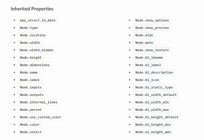
Screenshot of the Blender Python API docs on the Set Position Geometry Node page, cropped at the portion of the page showing the inherited properties on the class.
Through the base Node class, we have access to a lot of properties like the name of the node - or the width of it. Here’s what it’d look like accessing all those properties.
# Get object somehow
# Get the active object
obj = bpy.context.object

def handle_node_group(node_group):

    # Storage for all the node data we're exporting
    nodes_json = []

    # Loop through the nodes
    for node in node_group.nodes:
        print("Node", node.keys())
        print("Node props", dir(node))

        # Store any necessary node data
        node_data = {
            "type": node.type,
            "location": convert_vector_to_string(node.location),
            "width": node.width,
            "width_hidden": node.width_hidden,
            "height": node.height,
            "dimensions": node.dimensions,
            "name": node.name,
            "label": node.label,
            #"inputs": node.inputs,
            #"outputs": node.outputs,
            "internal_links": node.internal_links,
            "parent": node.parent,
            "use_custom_color": node.use_custom_color,
            "color": node.color,
            "select": node.select,
            "show_options": node.show_options,
            "show_preview": node.show_preview,
            "hide": node.hide,
            "mute": node.mute,
        }
        print("node_data", node_data)

        nodes_json.append(node_data)

    # See all the data
		print(nodes_json)

# Walk through object's "modifiers"
modifier = None
for modifier in obj.modifiers:
    if modifier.type == "NODES":
        print(modifier);
        print("modifier props:", dir(modifier))
        handle_node_group(modifier.node_group)
breakHere’s what that data looks like in JSON form for a Set Position node:
{
  "type": "SET_POSITION",
  "location": {
    "x": -54.20172119140625,
    "y": 96.60438537597656
  },
  "width": 140.0,
  "width_hidden": 0.0,
  "height": 100.0,
  "dimensions": {
    "x": 0.0,
    "y": 0.0
  },
  "name": "Set Position",
  "label": "",
  "inputs": [
    {
      "description": "",
      "display_shape": "CIRCLE",
      "enabled": true,
      "hide": false,
      "hide_value": false,
      "identifier": "Geometry",
      "is_linked": true,
      "is_multi_input": false,
      "is_output": false,
      "is_unavailable": false,
      "label": "",
      "link_limit": 1,
      "name": "Geometry",
      "node": "f192d339-9e7c-4b9c-aace-e3ebb322f764",
      "show_expanded": false,
      "type": "GEOMETRY"
    }
		// Couple more here...
  ],
  "outputs": [
    {
      "description": "",
      "display_shape": "CIRCLE",
      "enabled": true,
      "hide": false,
      "hide_value": false,
      "identifier": "Geometry",
      "is_linked": true,
      "is_multi_input": false,
      "is_output": true,
      "is_unavailable": false,
      "label": "",
      "link_limit": 4095,
      "name": "Geometry",
      "node": "f192d339-9e7c-4b9c-aace-e3ebb322f764",
      "show_expanded": false,
      "type": "GEOMETRY"
    }
  ],
  "parent": null,
  "use_custom_color": false,
  "color": {
    "r": 0.6079999804496765,
    "g": 0.6079999804496765,
    "b": 0.6079999804496765
  },
  "select": false,
  "show_options": true,
  "show_preview": false,
  "hide": false,
  "mute": false
},
Sweet, we have our nodes, but where’s the data “inside” the node? You know, the text inputs you can type into. That’s where “node sockets” come into play.
Node Sockets
What we’re most interested in however is the inputs and outputs properties, which contains the “sockets” on the left and right side. For example, the Combine XYZ node would have a 3 inputs and 1 output. The inputs and outputs share the same data structure called NodeSocket. You can see a sample of the data structure below, and the property names labeled on the node itself:
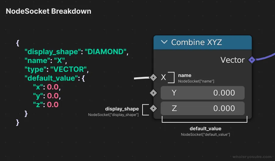
A diagram illustrating the path and properties for Node “sockets” superimposed on top of a Geometry Node and comparing it to the JSON output.
The primary thing we care about is the name and type of the field, which lets us know the name in the UI and what the data type is like Vector or Geometry. And if the input isn’t connected to anything and the user types in data, you can access that through default_value (e.g. the Y and Z text fields in the above picture).
Here’s an example of what that data looks like in JSON form:
{
  "description": "",
  "display_shape": "DIAMOND",
  "enabled": true,
  "hide": false,
  "hide_value": false,
  "identifier": "Offset",
  "is_linked": true,
  "is_multi_input": false,
  "is_output": false,
  "is_unavailable": false,
  "label": "",
  "link_limit": 1,
  "name": "Offset",
  "node": "f192d339-9e7c-4b9c-aace-e3ebb322f764",
  "show_expanded": false,
  "type": "VECTOR",
  "default_value": {
    "x": 4.20,
    "y": 0.0,
    "z": 0.0
  }
}
That’s all the relevant node data that we need for now, but feel free to explore the other properties. The Blender docs do a decent job of conveying what some properties do, and some are self explanatory (is_linked means “is the socket linked to something?”).
Node Links
If we go back to our top-level structure, we have nodes and links. The links represent the “connections” between all the nodes. So if I connect a Set Position node and it’s Geometry output socket to a Group Output node and it’s Geometry input socket, that’d be one “link”.
Links are represented by the NodeLink class. Each socket has a “from” and a “to” section. The node it’s coming “from”, and the node it’s going “to”. It also specifies the socket type, so it knows to connect it to the right one (e.g. geometry vs vector vs float). And we have a reference to the two nodes, the “from” node and the “to” node (so we know which node we’re talking about).
{
  "from_node": Node,
  "from_socket": {
    "type": "GEOMETRY",
    "node": Node
  },
  "to_node": Node,
  "to_socket": {
    "type": "GEOMETRY",
    "node": Node
  }
},
In this example we’re connecting two nodes together by their GEOMETRY sockets.
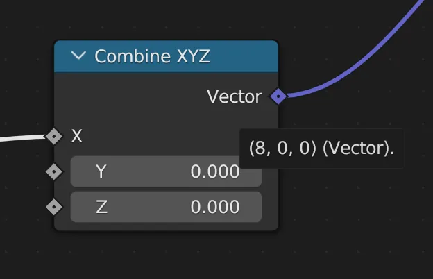
Getting evaluated data
It’s important to note here that sometimes we also have access to a property called default_value. This property represents the input or output data evaluated. This means it takes the input or output, and calculates every previous node, and provide you with the latest “crunched” data up to that point.
You can see a preview of this in the Blender UI by hovering over a property:
Screenshot of Blender UI in the Geometry Nodes showing a tooltip when hovering over a socket in a node
In order for a node to be evaluated, it needs to be connected to an output. If you try to hover over when it’s not connected, you’ll notice it can’t evaluate it:
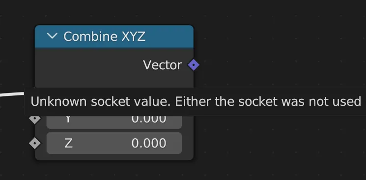
Screenshot of the error message tooltip displayed when hovering over a Geometry Node that isn’t connected to an output node.
We can access this data in code using the default_value property on our NodeSocket (aka the array items in node.inputs):
# Loop through links
for link in node_group.links:
    link_data = {
        "from_node": link.from_node["uuid"],
        "from_socket": {
            "type": link.from_socket.type,
            "node": link.from_socket.node["uuid"],
        },
        "to_node": link.to_node["uuid"],
        "to_socket": {
            "type": link.to_socket.type,
            "node": link.to_socket.node["uuid"],
        },
    }

    # Get any default data from input/outputs (e.g. 3D Vector “offset” in set position node)
    # FROM_SOCKET
    # We check if the default value exists (some slots don't have - like Geometry)
    if hasattr(link.from_socket, "default_value"):
        print("[FROM SOCKET] type:", type(link.from_socket.default_value))
        socket_value = convert_complex_type_to_json_format(link.from_socket.default_value)
        if socket_value:
            link_data["from_socket"]["default_value"] = socket_value

    # TO_SOCKET
    if hasattr(link.to_socket, "default_value"):
        print("[TO SOCKET] type:", type(link.to_socket.default_value))
        socket_value = convert_complex_type_to_json_format(link.to_socket.default_value)
        if socket_value:
            link_data["to_socket"]["default_value"] = socket_value

    output_json["links"].append(link_data)
Here’s what that data looks like in JSON:
{
  "from_node": Node,
  "from_socket": {
    "type": "VALUE",
    "node": Node,
    "default_value": "0.0"
  },
  "to_node": Node,
  "to_socket": {
    "type": "VALUE",
    "node": Node,
    "default_value": "0.0"
  }
},
This is a great way to get the “result” of a geometry node without having to do the calculations later.
Putting it all together
Now that we have an idea of how all the data looks and how to traverse it, let’s export it to JSON! This’ll be a little recap of some of the previous Python code.
Let’s grab the currently selected object, loop through it’s modifiers, and run a function called handle_node_group() for each Geometry Node modifier we find. There’s also a few imports at the top we’ll need later, like the json module.
import bpy, json, uuid, mathutils
from bpy import context
from pathlib import Path
from bpy_types import bpy_types

# SCRIPT BEGINS
# Get object somehow
# Get the active object
obj = bpy.context.object

# Walk through object's "modifiers"
modifier = None
for modifier in obj.modifiers:
    if modifier.type == "NODES":
        #print(modifier);
        #print("modifier props:", dir(modifier))
        handle_node_group(modifier.node_group)
        break
Now that we have the node group with the nodes and links, we can start parsing the data into JSON. Here’s what that handle_node_group() function looks like. The function takes a node_group (what the modifier returns - the nodes and links) and converts all the data to a JSON friendly format. There isn’t much converting you’ll notice, just more complex types like Vectors from Blender’s mathutil module.
We go through both the nodes and links and create a new object to store their data inside. We also do a secondary loop inside each node for the inputs and outputs, creating a separate object for their data as well.
Let’s take one second to breakdown the big thing I do here. I create a UUID for each node as we loop over them (str(uuid.uuid4())). But why?
Before I mentioned when we do the links, we know what node the socket is connected to because they “reference” the node. In code world, this it’s literally a reference to the instantiated class in memory - aka the same data we’re looping over. The one problem? Node’s don’t seem to have a unique ID associated with them. So there’s no way to tell them apart unless you’re comparing “reference” to “reference”. And since we’ll be exporting to JSON, we don’t have the luxury of keeping these memory references.
What’s the solution then? Creating a unique ID for each node (a UUID in this case) and applying that to the Node class in memory. So when we loop over the links later, the references to each node will also contain our ID (link.from_node["uuid"]), and we’ll save that to JSON. This allows us to associate nodes with links (just like data in a database!).
One other thing of note here is the hasattr() method checking for default_value. This is because some inputs don’t have a default value, like geometry. So you’ll need to check if this exists before accessing it.
def handle_node_group(node_group):

    output_json = {
        "nodes": [],
        "links": [],
    }
    # Storage for all the node data we're exporting
    nodes_json = []

    # Loop through the nodes
    for node in node_group.nodes:
        #print("Node", node.keys())
        #print("Node props", dir(node))
        node["uuid"] = str(uuid.uuid4())

        # Store any necessary node data
        node_output = {
            "uuid": node["uuid"],
            "type": node.type,
            "location": convert_vector_to_obj(node.location),
            "width": node.width,
            "width_hidden": node.width_hidden,
            "height": node.height,
            "dimensions": convert_vector_to_obj(node.dimensions),
            "name": node.name,
            "label": node.label,
            "inputs": [],
            "outputs": [],
            #"inputs": node.inputs,
            #"outputs": node.outputs,
            #"internal_links": node.internal_links,
            "parent": node.parent,
            "use_custom_color": node.use_custom_color,
            "color": convert_color_to_obj(node.color),
            "select": node.select,
            "show_options": node.show_options,
            "show_preview": node.show_preview,
            "hide": node.hide,
            "mute": node.mute,
        }

        # Loop through inputs and outputs and add those
        for input in node.inputs:
            # Store the input data
            input_data = {
                "description": input.description,
                "display_shape": input.display_shape,
                #"default_value": input.default_value,
                #"draw": input.draw,
                #"draw_color": input.draw_color,
                "enabled": input.enabled,
                "hide": input.hide,
                "hide_value": input.hide_value,
                "identifier": input.identifier,
                "is_linked": input.is_linked,
                "is_multi_input": input.is_multi_input,
                "is_output": input.is_output,
                "is_unavailable": input.is_unavailable,
                "label": input.label,
                "link_limit": input.link_limit,
                "name": input.name,
                "node": input.node["uuid"],
                #"rna_type": input.rna_type,
                "show_expanded": input.show_expanded,
                "type": input.type,
            }

            # Check if it has a default value - this is the user input node data
            if hasattr(input, "default_value"):
                print("input default_value", input.default_value)
                input_data["default_value"] = convert_complex_type_to_json_format(input.default_value)

            # Add data to node inputs
            node_output["inputs"].append(input_data)


        for output in node.outputs:
            print("[OUTPUT]:", dir(output))
            # Store the input data
            output_data = {
                "description": output.description,
                "display_shape": output.display_shape,
                #"default_value": output.default_value,
                #"draw": input.draw,
                #"draw_color": input.draw_color,
                "enabled": output.enabled,
                "hide": output.hide,
                "hide_value": output.hide_value,
                "identifier": output.identifier,
                "is_linked": output.is_linked,
                "is_multi_input": output.is_multi_input,
                "is_output": output.is_output,
                "is_unavailable": output.is_unavailable,
                "label": output.label,
                "link_limit": output.link_limit,
                "name": output.name,
                "node": output.node["uuid"],
                #"rna_type": input.rna_type,
                "show_expanded": output.show_expanded,
                "type": output.type,
            }

            # Check if it has a default value - this is the user input node data
            if hasattr(output, "default_value"):
                print("output default_value", output.default_value)
                output_data["default_value"] = convert_complex_type_to_json_format(output.default_value)

            # Add data to node inputs
            node_output["outputs"].append(output_data)

        #print("node_output", node_output)
        nodes_json.append(node_output)

    output_json["nodes"] = nodes_json

    # Loop through links
    for link in node_group.links:
        link_data = {
            "from_node": link.from_node["uuid"],
            "from_socket": {
                "type": link.from_socket.type,
                "node": link.from_socket.node["uuid"],
            },
            "to_node": link.to_node["uuid"],
            "to_socket": {
                "type": link.to_socket.type,
                "node": link.to_socket.node["uuid"],
            },
        }

        # Get any default data from input/outputs (e.g. 3D Vector “offset” in set position node)
        # FROM_SOCKET
        # We check if the default value exists (some slots don't have - like Geometry)
        if hasattr(link.from_socket, "default_value"):
            print("[FROM SOCKET] type:", type(link.from_socket.default_value))
            socket_value = convert_complex_type_to_json_format(link.from_socket.default_value)
            if socket_value:
                link_data["from_socket"]["default_value"] = socket_value

        # TO_SOCKET
        if hasattr(link.to_socket, "default_value"):
            print("[TO SOCKET] type:", type(link.to_socket.default_value))
            socket_value = convert_complex_type_to_json_format(link.to_socket.default_value)
            if socket_value:
                link_data["to_socket"]["default_value"] = socket_value

        output_json["links"].append(link_data)

# Walk through object's "modifiers"
modifier = None
for modifier in obj.modifiers:
    if modifier.type == "NODES":
        #print(modifier);
        #print("modifier props:", dir(modifier))
        handle_node_group(modifier.node_group)
        break
I had to make a few helper functions to handle the conversion from complex types to primitive JSON types. Usually math classes like Vector will have a conversion methods to other formats, but Blender’s didn’t. I feel like there’s probably a good niche community resource for this out there 🤔
But something of note here is the use of isinstance() to decipher what type the default_value is. I pass in the class or type and it’ll let me know if it matches (like checking for a Vector vs float). Nothing too wild here, just some code trying to be clever (like a function to handle any dimension of vector, from 1D to 4D) but probably not if you actually know good Python 😅
def convert_color_to_obj(color):
    color_obj = {}

    if hasattr(color, "r"):
        color_obj["r"] = color.r

    if hasattr(color, "g"):
        color_obj["g"] = color.g

    if hasattr(color, "b"):
        color_obj["b"] = color.b

    if hasattr(color, "a"):
        color_obj["a"] = color.a

    return color_obj

def convert_vector_to_obj(vector_value):
    vector_obj = {}

    if hasattr(vector_value, "x"):
        vector_obj["x"] = vector_value.x

    if hasattr(vector_value, "y"):
        vector_obj["y"] = vector_value.y

    if hasattr(vector_value, "z"):
        vector_obj["z"] = vector_value.z

    if hasattr(vector_value, "w"):
        vector_obj["w"] = vector_value.w

    return vector_obj

# Convert complex types into JSON compatible formats
def convert_complex_type_to_json_format(default_value):
    if isinstance(default_value, mathutils.Vector):
        return convert_vector_to_obj(default_value)

    if isinstance(default_value, float):
        return "{}".format(default_value)

    if isinstance(default_value, bpy_types.bpy_prop_array):
        socket_array = []
        for socket_value in default_value:
            socket_array.append("{}".format(socket_value))
        return socket_array
Cool, we have an object stuffed with our nodes and links. Now we just export it to a JSON file. At a high level we’ll grab the current file path, create a JSON file in there, use the same name as our Blender file, and increment the filename (e.g. Test-nodes-1.json).
We grab the path of the current file from Blender’s context (bpy.context.blend_data.filepath). Then we pass it to the Path() module, this gives us handy methods like with_suffix() to change the file extension quickly. Since we need the filename itself (e.g. Test from Test.blend) we use the with_suffix() with a blank string to remove the extension.
I also don’t want to override any existing JSON files, so we do a quick while loop checking if the path exists. I know this looks nasty with how long the parameter is, but I couldn’t find a good way to store the value in a variable and have it update each loop (maybe a Python thing?). Then we just open() the file path and json.dump() our data in.
# Get path of current file
file_index = 0
blend_path = Path(bpy.context.blend_data.filepath)
# Grab the file name
blend_file_name = blend_path.with_suffix("").name;
# The template for the final JSON filename
name_template = "{}-nodes-{}"

# Check if file exists - increment if so
while blend_path.with_name(name_template.format(blend_file_name, file_index)).with_suffix(".json").exists():
    file_index += 1

# Create a file name with a number appended (e.g. your-file-01)
blend_versioned_name = name_template.format(blend_file_name, file_index)
# Creates a JSON path using current filename + location
json_path = blend_path.with_name(blend_versioned_name).with_suffix(".json")

# Open the file and dump the JSON data to it
# using "x" instead of "w" to error if the file already exists, though very unlikely due to line 29
with open(json_path, "x") as f:
    json.dump(output_json, f)
And that’s kinda it. We have all of the relevant geometry node data we need in a JSON format, readily accessibly by any other app.
Here’s a link to the final script if you want to copy/paste the whole thing. And here’s a link to an example JSON output of a basic geometry node graph.
What’s next?
The next step is actually making an app to consume this JSON! I’ll make a small React app that displays the geometry nodes on the web using the JSON data.
Here’s an example of the app we’ll be building in the next tutorial:
A web based geometry node graph.
Keep your eyes peeled on my Mastodon or Instagram stories to know when the next post drops!
What are you building?
I’m always curious to see what you’re building with geometry nodes, node graphs, or 3D in general, just xeet or toot me a link or screenshot.
And thanks for reading! Hope this helped you understand Blender’s Geometry Nodes and their Python API a bit better, and ideally save you some time grokking everything with helpful diagrams 😁
Stay curious, Ryo